PLC network diagram
Article#: 00086
Date: 2024-02-08
Author: Radim
What is a PLC network diagram and what is it good for?
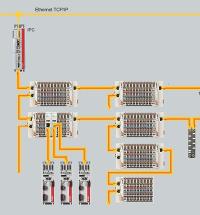
A PLC network diagram is a visual representation of the entire automation system, encompassing PLCs, input/output modules, communication networks, devices, and power supplies.
It serves as a high-level visualization tool that depicts the architecture and connectivity of an industrial automation system.
It provides on a single sheet a comprehensive overview of how components are interconnected and communicate within the system, offering numerous benefits for stakeholders involved in the automation process.
PLC network diagrams are invaluable for:
1. Visualization: Providing a visual representation of the entire automation system, including PLCs, I/O modules, communication networks, and other devices.
2. System design: Assisting engineers in planning the layout of components and communication pathways within the automation system.
3. Troubleshooting: Aiding technicians in identifying and diagnosing issues within the system, leading to faster resolution and reduced downtime.
4. Maintenance: Guiding maintenance personnel in performing routine maintenance tasks and updates on system components.
5. Documentation: Serving as a comprehensive reference for documenting system architecture, configurations, and revisions.
6. Communication: Facilitating collaboration and communication among people involved in the design, implementation, and maintenance of the automation system.
How should a useful PLC network diagram look?
A useful PLC network diagram should incorporate several key elements to ensure clarity, comprehensiveness, and effectiveness:
1. Component representation: Include icons or images representing PLCs, I/O modules, devices, and other components within the automation system.
2. Component names and labels: Clearly label each component with its name, identifier, or function to aid understanding and identification.
3. IP addresses and node numbers: Include IP addresses for devices on Ethernet-based networks and node numbers for devices on other communication protocols.
This information helps in configuring, identifying, and troubleshooting devices within the network.
4. Power supplies: Show individual power supplies and their connections to components within the system.
5. Connection pathways: Illustrate communication pathways between components, including wired and wireless connections.
6. Communication networks: Depict communication networks such as Ethernet, Profibus, Modbus, etc., and show connections between components and network devices.
7. Color notation: Use color coding to differentiate between different types of bus cables or communication networks, enhancing visual clarity and comprehension.
8. Legend or key: Include a legend or key within the diagram to explain the meaning of symbols, colors, IP addresses, node numbers, and labels used.
9. Consistency and accuracy: Maintain consistency in notation, labeling, and representation throughout the diagram to ensure clarity and accuracy.
© Radim-Automation, 2020–2026. All rights reserved.
Sharing of this article is permitted with proper attribution (link to the original page).
Related previous articles:
- Diagnostic tools
- Event logger as the very first function implemented in the program
- It doesn't work without sensors
- Clear signals
- Design considerations for effective HMIS
- Safety relays versus safety PLC
- Documentation issues
- Visual modeling
- Machine modularization
- Abbreviations
- Modular software architecture
- Hardware concept
- A good concept = Complete set of suitable solutions
- Are there also any disadvantages?
- Design machines with a focus on user's abilities and needs
- More than just start and stop
- Safety first!
- Introduce the terminology and standardize it!
- Industrial evolution - Listen to your customers and follow new trends!
- Have an expert on hand!
- Focus on target!
- Think on paper!
- Sharpen your axe before you start felling!
- Keep it simple!
- Transparency and reliability
- From an idea to a consistent system
Related next articles:
- Keep the documentation up to date throughout the project
- Dream of a platform-independent PLC program
- Keep everything you need together
- Hidden dangers during commissioning
- When a touch panel isn't enough
- Resilient machine control design
- How long will a failure keep our production down?
- Redundant PLC – Yes or No?
- Buttons: Start, Stop and one more
- Different types of machine stops
- Safety stops must have the highest priority
- Danger! Unexpected machine start
- Buttons reset and start